Epicyclic gearing

An epicyclic gear train (also known as a planetary gearset) is a gear reduction assembly consisting of two gears mounted so that the center of one gear (the "planet") revolves around the center of the other (the "sun"). A carrier connects the centers of the two gears and rotates, to carry the planet gear(s) around the sun gear. The planet and sun gears mesh so that their pitch circles roll without slip. If the sun gear is held fixed, then a point on the pitch circle of the planet gear traces an epicycloid curve.
An epicyclic gear train can be assembled so the planet gear rolls on the inside of the pitch circle of an outer gear ring, or ring gear, sometimes called an annulus gear. Such an assembly of a planet engaging both a sun gear and a ring gear is called a planetary gear train.[1][2] By choosing to hold one component or another—the planetary carrier, the ring gear, or the sun gear—stationary, three different gear ratios can be realized.[3]
Overview
[edit]
Epicyclic gearing or planetary gearing is a gear system consisting of one or more outer, or planet, gears or pinions, revolving about a central sun gear or sun wheel.[4][5] Typically, the planet gears are mounted on a movable arm or carrier, which itself may rotate relative to the sun gear. Epicyclic gearing systems also incorporate the use of an outer ring gear or annulus, which meshes with the planet gears. Planetary gears (or epicyclic gears) are typically classified as simple or compound planetary gears. Simple planetary gears have one sun, one ring, one carrier, and one planet set. Compound planetary gears involve one or more of the following three types of structures: meshed-planet (there are at least two more planets in mesh with each other in each planet train), stepped-planet (there exists a shaft connection between two planets in each planet train), and multi-stage structures (the system contains two or more planet sets). Compared to simple planetary gears, compound planetary gears have the advantages of larger reduction ratio, higher torque-to-weight ratio, and more flexible configurations.[6]
The axes of all gears are usually parallel, but for special cases like pencil sharpeners and differentials, they can be placed at an angle, introducing elements of bevel gear (see below). Further, the sun, planet carrier and ring axes are usually coaxial.

Epicyclic gearing is also available which consists of a sun, a carrier, and two planets which mesh with each other. One planet meshes with the sun gear, while the second planet meshes with the ring gear. For this case, when the carrier is fixed, the ring gear rotates in the same direction as the sun gear, thus providing a reversal in direction compared to standard epicyclic gearing.
History
[edit]Around 500 BC, the Greeks invented the idea of epicycles, of circles travelling on the circular orbits. With this theory Claudius Ptolemy in the Almagest in 148 AD was able to approximate planetary paths observed crossing the sky. The Antikythera Mechanism, circa 80 BC, had gearing which was able to closely match the Moon's elliptical path through the heavens, and even to correct for the nine-year precession of that path.[7] (The Greeks interpreted the motion they saw, not as elliptical, but rather as epicyclic motion.)
In the 2nd century AD treatise The Mathematical Syntaxis (a.k.a. Almagest), Claudius Ptolemy used rotating deferent and epicycles that form epicyclic gear trains to predict the motions of the planets. Accurate predictions of the movement of the Sun, Moon, and the five planets, Mercury, Venus, Mars, Jupiter, and Saturn, across the sky assumed that each followed a trajectory traced by a point on the planet gear of an epicyclic gear train. This curve is called an epitrochoid.[citation needed]
Epicyclic gearing was used in the Antikythera Mechanism, circa 80 BC, to adjust the displayed position of the Moon for the ellipticity of its orbit, and even for its orbital apsidal precession. Two facing gears were rotated around slightly different centers; one drove the other, not with meshed teeth but with a pin inserted into a slot on the second. As the slot drove the second gear, the radius of driving would change, thus invoking a speeding up and slowing down of the driven gear in each revolution.[citation needed]
Richard of Wallingford, an English abbot of St. Albans monastery, later described epicyclic gearing for an astronomical clock in the 14th century.[8] In 1588, Italian military engineer Agostino Ramelli invented the bookwheel, a vertically revolving bookstand containing epicyclic gearing with two levels of planetary gears to maintain proper orientation of the books.[8][9]
French mathematician and engineer Desargues designed and constructed the first mill with epicycloidal teeth c. 1650.[10]
Requirements for non-interference
[edit]In order that the planet gear teeth mesh properly with both the sun and ring gears, assuming equally spaced planet gears, the following equation must be satisfied:
where
are the number of teeth of the sun gear and the ring gear, respectively and
is the number of planet gears in the assembly and
is a whole number
If one is to create an asymmetric carrier frame with non-equiangular planet gears, say to create some kind of mechanical vibration in the system, one must make the teething such that the above equation complies with the "imaginary gears". For example, in the case where a carrier frame is intended to contain planet gears spaced 0°, 50°, 120°, and 230°, one is to calculate as if there are actually 36 planetary gears (10° equiangular), rather than the four real ones.
Gear speed ratios of conventional epicyclic gearing
[edit]The gear ratio of an epicyclic gearing system is somewhat non-intuitive, particularly because there are several ways in which an input rotation can be converted into an output rotation. The four basic components of the epicyclic gear are:
- Sun gear: The central gear
- Carrier frame: Holds one or more planetary gear(s) symmetrically and separated, all meshed with the sun gear
- Planet gear(s): Usually two to four peripheral gears, all of the same size, that mesh between the sun gear and the ring gear
- Ring gear, Moon gear, Annulus gear, or Annular gear: An outer ring with inward-facing teeth that mesh with the planetary gear(s)

The overall gear ratio of a simple planetary gearset can be calculated using the following two equations,[1] representing the sun-planet and planet-ring interactions respectively:
where
- are the angular velocities of the ring gear, sun gear, planetary gears, and carrier frame respectively, and are the number of teeth of the ring gear, the sun gear, and each planet gear respectively.
from which we can derive the following:
and
only if [11] In many epicyclic gearing systems, one of these three basic components is held stationary (hence set for whichever gear is stationary); one of the two remaining components is an input, providing power to the system, while the last component is an output, receiving power from the system. The ratio of input rotation to output rotation is dependent upon the number of teeth in each of the gears, and upon which component is held stationary.
Alternatively, in the special case where the number of teeth on each gear meets the relationship the equation can be re-written as the following:
where
- is the sun-to-planet gear ratio.
These relationships can be used to analyze any epicyclic system, including those, such as hybrid vehicle transmissions, where two of the components are used as inputs with the third providing output relative to the two inputs.[12]
In one arrangement, the planetary carrier (green in the diagram above) is held stationary, and the sun gear (yellow) is used as input. In that case, the planetary gears simply rotate about their own axes (i.e., spin) at a rate determined by the number of teeth in each gear. If the sun gear has teeth, and each planet gear has teeth, then the ratio is equal to For instance, if the sun gear has 24 teeth, and each planet has 16 teeth, then the ratio is −+24/ 16 , or −+3/ 2 ; this means that one clockwise turn of the sun gear produces 1.5 counterclockwise turns of each of the planet gear(s) about its axis.
Rotation of the planet gears can in turn drive the ring gear (not depicted in diagram), at a speed corresponding to the gear ratios: If the ring gear has teeth, then the ring will rotate by turns for each turn of the planetary gears. For instance, if the ring gear has 64 teeth, and the planets 16 teeth, one clockwise turn of a planet gear results in 16/ 64 , or 1/ 4 clockwise turns of the ring gear. Extending this case from the one above:
- One turn of the sun gear results in turns of the planets
- One turn of a planet gear results in turns of the ring gear
So, with the planetary carrier locked, one turn of the sun gear results in turns of the ring gear.
The ring gear may also be held fixed, with input provided to the planetary gear carrier; output rotation is then produced from the sun gear. This configuration will produce an increase in gear ratio, equal to
If the ring gear is held stationary and the sun gear is used as the input, the planet carrier will be the output. The gear ratio in this case will be which may also be written as This is the lowest gear ratio attainable with an epicyclic gear train. This type of gearing is sometimes used in tractors and construction equipment to provide high torque to the drive wheels.
In bicycle hub gears, the sun is usually stationary, being keyed to the axle or even machined directly onto it. The planetary gear carrier is used as input. In this case the gear ratio is simply given by The number of teeth in the planet gear is irrelevant.
Accelerations of standard epicyclic gearing
[edit]From the above formulae, we can also derive the accelerations of the sun, ring and carrier, which are:
Torque ratios of standard epicyclic gearing
[edit]In epicyclic gears, two speeds must be known in order to determine the third speed. However, in a steady state condition, only one torque must be known in order to determine the other two torques. The equations which determine torque are:
where: — Torque of ring (annulus), — Torque of sun, — Torque of carrier. For all three, these are the torques applied to the mechanism (input torques). Output torques have the reverse sign of input torques. These torque ratios can be derived using the law of conservation of energy. Applied to a single stage this equation is expressed as:
In the cases where gears are accelerating, or to account for friction, these equations must be modified.
Fixed carrier train ratio
[edit]A convenient approach to determine the various speed ratios available in a planetary gear train begins by considering the speed ratio of the gear train when the carrier is held fixed. This is known as the fixed carrier train ratio.[2]
In the case of a simple planetary gear train formed by a carrier supporting a planet gear engaged with a sun and ring gear, the fixed carrier train ratio is computed as the speed ratio of the gear train formed by the sun, planet and ring gears on the fixed carrier. This is given by
In this calculation the planet gear is an idler gear.
The fundamental formula of the planetary gear train with a rotating carrier is obtained by recognizing that this formula remains true if the angular velocities of the sun, planet and ring gears are computed relative to the carrier angular velocity. This becomes,
This formula provides a simple way to determine the speed ratios for the simple planetary gear train under different conditions:
1. The carrier is held fixed, ωc=0,
2. The ring gear is held fixed, ωr=0,
3. The sun gear is held fixed, ωs=0,
Each of the speed ratios available to a simple planetary gear train can be obtained by using band brakes to hold and release the carrier, sun or ring gears as needed. This provides the basic structure for an automatic transmission.
Spur gear differential
[edit]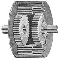
A spur gear differential is constructed from two identical coaxial epicyclic gear trains assembled with a single carrier such that their planet gears are engaged. This forms a planetary gear train with a fixed carrier train ratio R = −1.
In this case, the fundamental formula for the planetary gear train yields,
or
Thus, the angular velocity of the carrier of a spur gear differential is the average of the angular velocities of the sun and ring gears.
In discussing the spur gear differential, the use of the term ring gear is a convenient way to distinguish the sun gears of the two epicyclic gear trains. Ring gears are normally fixed in most applications as this arrangement will have a good reduction capacity. The second sun gear serves the same purpose as the ring gear of a simple planetary gear train but clearly does not have the internal gear mate that is typical of a ring gear.[1]
Gear ratio of reversed epicyclic gearing
[edit]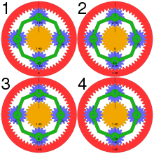
Some epicyclic gear trains employ two planetary gears which mesh with each other. One of these planets meshes with the sun gear, the other planet meshes with the ring gear. This results in different ratios being generated by the planetary and also causes the sun gear to rotate in the same direction as the ring gear when the planet carrier is the stationary. The fundamental equation becomes:
where
which results in:
- when the carrier is locked,
- when the sun is locked,
- when the ring gear is locked.
Compound planetary gears
[edit]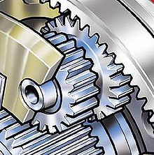
"Compound planetary gear" is a general concept and it refers to any planetary gears involving one or more of the following three types of structures: meshed-planet (there are at least two or more planets in mesh with each other in each planet train), stepped-planet (there exists a shaft connection between two planets in each planet train), and multi-stage structures (the system contains two or more planet sets).
Some designs use "stepped-planet" which have two differently-sized gears on either end of a common shaft. The small end engages the sun, while the large end engages the ring gear. This may be necessary to achieve smaller step changes in gear ratio when the overall package size is limited. Compound planets have "timing marks" (or "relative gear mesh phase" in technical term). The assembly conditions of compound planetary gears are more restrictive than simple planetary gears,[13] and they must be assembled in the correct initial orientation relative to each other, or their teeth will not simultaneously engage the sun and ring gear at opposite ends of the planet, leading to very rough running and short life. In 2015, a traction based variant of the "stepped-planet" design was developed at the Delft University of Technology,[14] which relies on compression of the stepped planet elements to achieve torque transmission. The use of traction elements eliminates the need to "timing marks" as well as the restrictive assembly conditions as typically found. Compound planetary gears can easily achieve larger transmission ratio with equal or smaller volume. For example, compound planets with teeth in a 2:1 ratio with a 50T ring gear would give the same effect as a 100T ring gear, but with half the actual diameter.
More planet and sun gear units can be placed in series in the same housing (where the output shaft of the first stage becomes the input shaft of the next stage) providing a larger (or smaller) gear ratio. This is the way most automatic transmissions work. In some cases multiple stages may even share the same ring gear which can be extended down the length of the transmission, or even be a structural part of the casing of smaller gearboxes.
During World War II, a special variation of epicyclic gearing was developed for portable radar gear, where a very high reduction ratio in a small package was needed. This had two outer ring gears, each half the thickness of the other gears. One of these two ring gears was held fixed and had one tooth fewer than did the other. Therefore, several turns of the "sun" gear made the "planet" gears complete a single revolution, which in turn made the rotating ring gear rotate by a single tooth like a cycloidal drive.[citation needed]
Power splitting
[edit]More than one member of a system can serve as an output. As an example, the input is connected to the ring gear, the sun gear is connected to the output and the planet carrier is connected to the output through a torque converter. Idler gears are used between sun gear and the planets to cause the sun gear to rotate in the same direction as the ring gear when the planet carrier is stationary. At low input speed, because of the load on the output, the sun will be stationary and the planet carrier will rotate in the direction of the ring gear. Given a high enough load, the turbine of the torque converter will remain stationary, the energy will be dissipated and the torque converter pump will slip. If the input speed is increased to overcome the load the converter turbine will turn the output shaft. Because the torque converter itself is a load on the planet carrier, a force will be exerted on the sun gear. Both the planet carrier and the sun gear extract energy from the system and apply it to the output shaft.[15]
Advantages
[edit]
Planetary gear trains provide high power density in comparison to standard parallel axis gear trains. They provide a reduction in volume, multiple kinematic combinations, purely torsional reactions, and coaxial shafting. Disadvantages include high bearing loads, constant lubrication requirements, inaccessibility, and design complexity.[16][17]
The efficiency loss in a planetary gear train is typically about 3% per stage. This type of efficiency ensures that a high proportion (about 97%) of the energy being input is transmitted through the gearbox, rather than being wasted on mechanical losses inside the gearbox.
The load in a planetary gear train is shared among multiple planets; therefore, torque capability is greatly increased. The more planets in the system, the greater the load ability and the higher the torque density.
The planetary gear train also provides stability due to an even distribution of mass and increased rotational stiffness. Torque applied radially onto the gears of a planetary gear train is transferred radially by the gear, without lateral pressure on the gear teeth.
In a typical application, the drive power connects to the sun gear. The sun gear then drives the planetary gears assembled with the external gear ring to operate. The whole set of planetary gear system revolves on its own axis and along the external gear ring where the output shaft connected to the planetary carrier achieves the goal of speed reduction. A higher reduction ratio can be achieved by doubling the multiple staged gears and planetary gears which can operate within the same ring gear.
The method of motion of a planetary gear structure is different from traditional parallel gears. Traditional gears rely on a small number of contact points between two gears to transfer the driving force. In this case, all the loading is concentrated on a few contacting surfaces, making the gears wear quickly and sometimes crack. But the planetary speed reducer has multiple gear contacting surfaces with a larger area that can distribute the loading evenly around the central axis. Multiple gear surfaces share the load, including any instantaneous impact loading, evenly, which makes them more resistant to damage from higher torque. The housing and bearing parts are also less likely to be damaged from high loading as only the planet carrier bearings experience significant lateral force from the transmission of torque, radial forces oppose each other and are balanced, and axial forces only arise when using helical gears.
3D printing
[edit]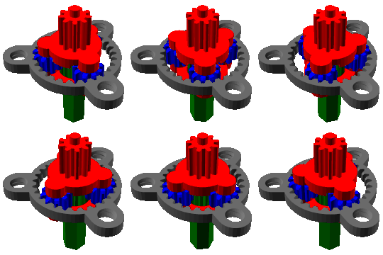
Planetary gears have become popular in the maker community, due to their inherent high torque capabilities and compactness/efficiency[18]. Especially within 3D printing, they can be used to rapidly prototype a gear box, to then be manufactured with machining technologies later.[19]
A geared-down motor must turn farther and faster in order to produce the same output movement in the 3D printer which is advantageous if it is not outweighed by the slower movement speed. If the stepper motor has to turn farther then it also has to take more steps to move the printer a given distance; therefore, the geared-down stepper motor has a smaller minimum step-size than the same stepper motor without a gearbox. While down-gearing improves precision in unidirectional motion, it adds backlash to the system and so reduces its absolute positioning accuracy.[20]
Since herringbone gears are easy to 3D print, it has become very popular to 3D print a moving herringbone planetary gear system for teaching children how gears work. An advantage of herringbone gears is that they don't fall out of the ring and don't need a mounting plate, allowing the moving parts to be clearly seen.
Gallery
[edit]-
Split ring, compound planet, epicyclic gears of a car rear-view mirror positioner. This has a ratio from input sun gear to output black ring gear of −5/352.
-
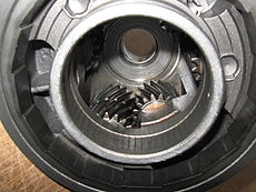
Reduction gears on Pratt & Whitney Canada PT6 gas turbine engine.
-
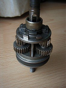
One of three sets of three gears inside the planet carrier of a Ford FMX Ravigneaux transmission
See also
[edit]- Hypocycloidal gearing
- Antikythera mechanism – ancient mechanical astronomical computer
- Continuously variable transmission (CVT)
- Cycloidal drive
- Epicycloid
- Ford Model T – had a 2 speed planetary transmission.
- Gearbox
- Harmonic drive
- Hub gear, for bicycles, etc.
- NuVinci continuously variable transmission
- Ravigneaux planetary gearset
- Lepelletier gear mechanism
- Rohloff Speedhub – 14-ratio bicycle hub gearbox
- Simpson planetary gearset
- Sturmey Archer – First major manufacturer of bicycle hubs using planetary gears
- Uni Wheel - a wheel that incorporates a planetary gear system
References
[edit]- ^ a b c J. J. Uicker, G. R. Pennock and J. E. Shigley, 2003, Theory of Machines and Mechanisms, Oxford University Press, New York.
- ^ a b B. Paul, 1979, Kinematics and Dynamics of Planar Machinery, Prentice Hall.
- ^ Machinery, Volume 19. University of California. 1913. p. 979.
- ^ Hillier, V.A.W. (2001). "Planetary gearing and unidirectional clutches". Fundamentals of Motor Vehicle Technology (4th ed.). Cheltenham, UK: Nelson Thornes. p. 244. ISBN 0-74-870531-7.
- ^ Harrison, H.; Nettleton, T. (1994). Principles of Engineering Mechanics (2nd ed.). Oxford, UK: Butterworth-Heinemann. p. 58. ISBN 0-34-056831-3.
- ^ "What are planetary gears and how do they work". Power Transmission Components. Retrieved 2024-09-25.
- ^ Wright, M.T. (2007). "The Antikythera Mechanism reconsidered" (PDF). Interdisciplinary Science Reviews. 32 (1): 27–43. Bibcode:2007ISRv...32...27W. doi:10.1179/030801807X163670. S2CID 54663891. Retrieved 20 May 2014.
- ^ a b Coy, J.J.; Townsend, D.P.; Zaretsky, E.V. (1985). Gearing (PDF) (Report). NASA Reference Publication. Vol. 1152. AVSCOM Technical Report 84-C-15.
- ^ Randl, Chad (15 May 2008). Revolving Architecture: A history of buildings that rotate, swivel, and pivot. New York, NY: Princeton Architectural Press. p. 19. ISBN 978-156898681-4. OCLC 1036836698. ISBN 1568986815
- ^ Musson, A.E.; Robinson, Eric H. (1969). Science and Technology in the Industrial Revolution. Toronto, ON: University of Toronto Press. p. 69. ISBN 9780802016379. OCLC 1036858215.
- ^ "How to derive and calculate epicyclic gear ratio equations in planetary gear systems". buseco.net.
- ^ Miller, John M. (May 2006). "Hybrid electric vehicle propulsion system architectures of the e-CVT type". IEEE Transactions on Power Electronics. 21 (3): 756–767. Bibcode:2006ITPE...21..756M. doi:10.1109/TPEL.2006.872372. S2CID 4986932.
- ^ P. A. Simionescu (1998-09-01). "A Unified Approach to the Assembly Condition of Epicyclic Gears". Journal of Mechanical Design. 120 (3): 448–453. doi:10.1115/1.2829172.
- ^ "Archimedes Drive".
- ^ "52514 Caterpillar Tractor D8 Bulldozer Powershift Transmission Promotional Film". 10 August 2022.
- ^ Lynwander, P., 1983, Gear Drive Systems: Design and Application. Marcel Dekker, New York
- ^ Smith, J. D., 1983, Gears and Their Vibration: A Basic Approach to Understanding Gear Noise. Marcel Dekker, New York and MacMillan, London
- ^ MECHTEX. "Planetary Gearbox | Introduction and Construction". MECHTEX. Retrieved 2025-01-03.
- ^ Amer, Mohammed; Lin, Chung-Cheng; Ismail, Hasan; Wu, Shin-Hung (2024-02-01). "Planetary Gearbox Design and Development using Additive Manufacturing". An-Najah University Journal for Research: 52 – via ResearchGate.
- ^ "Which factors affect the accuracy of the planetary gearbox? | GearKo Reducers" (in Chinese (China)). Retrieved 2025-01-03.
External links
[edit]- Kinematic Models for Design Digital Library (KMODDL), movies and photos of hundreds of working mechanical-systems models at Cornell.
- "Epicyclic gearing animation in SVG"
- "Animation of Epicyclic gearing"
- The "Power Split Device"
- The "Interactive Planetary Gearset tutorial"
- Prius Gearbox
- Planetary Gearbox
- Short Cuts for Analyzing Planetary Gearing Archived 2021-02-25 at the Wayback Machine


