Partial dislocation
This article may be too technical for most readers to understand. (April 2021) |
In materials science, a partial dislocation is a decomposed form of dislocation that occurs within a crystalline material. An extended dislocation is a dislocation that has dissociated into a pair of partial dislocations. The vector sum of the Burgers vectors of the partial dislocations is the Burgers vector of the extended dislocation.
Reaction favorability
[edit]A dislocation will decompose into partial dislocations if the energy state of the sum of the partials is less than the energy state of the original dislocation. This is summarized by Frank's Energy Criterion:
Shockley partial dislocations
[edit]Shockley partial dislocations generally refer to a pair of dislocations which can lead to the presence of stacking faults. This pair of partial dislocations can enable dislocation motion by allowing an alternate path for atomic motion.
In FCC systems, an example of Shockley decomposition is:
Which is energetically favorable:
The components of the Shockley Partials must add up to the original vector that is being decomposed:
Frank partial dislocations
[edit]Frank partial dislocations are sessile (immobile), but can move by diffusion of atoms.[1] In FCC systems, Frank partials are given by:
Thompson tetrahedron
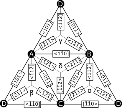
[edit]For FCC crystals, Thompson tetrahedrons or Thompson notation are an invented notation for more easily describing partial dislocations. In a given unit cell, mark point A at the origin, point B at a/2 [110], point C at a/2[011], and point D at a/2[101]--these points form the vertices of a tetrahedron. Then, mark the center of the opposite faces for each point as α, β, γ, and δ, respectively.[2] With this, the geometric representation of a Thompson tetrahedron is complete.

Any combination of Roman letters describes a member of the {111} slip planes in an FCC crystal. A vector made from two Roman letters describes the Burgers vector of a perfect dislocation. If the vector is made from a Roman letter and a Greek letter, then it is a Frank partial if the letters are corresponding (Aα, Bβ,...) or a Shockley partial otherwise (Aβ, Aγ,...). Vectors made from two Greek letters describe stair-rod dislocations. Using Thompson notation, Burgers vectors can be added to describe other dislocations and mechanisms. For example, two Shockley partial dislocations can be added to form a perfect dislocation: Aβ + βC = AC.[2] It is necessary that the interior letters of a given operation match, but many can be added in sequence to describe more complex mechanisms.
It is useful to summarize this information using an unfolded Thompson tetrahedron.

Lomer–Cottrell lock
[edit]The Lomer-Cottrell dislocation forms via a more complex dislocation reaction. For example, consider two extended dislocations: DB = Dγ + γB and BC = Bδ + δC. When they meet, it is more energetically favorable to form a single dislocation, DC = DB + BC = Dγ + γB + Bδ + δC = Dγ + γδ + δC. The trailing partials of each extended dislocation now form a stair-rod partial. This structure leads to reduced mobility of the dislocations as the core structure is non-planar (meaning it doesn’t cross along the face of the tetrahedron).[2] This reduction of mobility transforms the Lomer-Cottrell dislocation into an obstacle for other dislocations, thus strengthening the material.
Mechanical implications
[edit]When forming stacking faults, the partial dislocations reach an equilibrium when the repulsive energy between partial dislocations matches the attractive energy of the stacking fault. This means that higher stacking fault energy materials, i.e. those with high shear modulus and large Burgers vectors, will have smaller distance between partial dislocations. Conversely, low stacking fault energy materials will have large distances between partial dislocations.[3]

In order to cross slip, both partial dislocations need to change slip planes. The common Friedel-Escaig mechanism requires that the partial dislocations recombine at a point before cross slipping onto a different slip plane.[2] Bringing the partials together entails applying sufficient shear stress to reduce the distance between them, so partial dislocations with low stacking fault energies will inherently be more difficult to bring together and thus more difficult to cross slip.[3][4] Conversely, high stacking fault energy materials will be easier to cross slip.
The more easily a dislocation can cross slip, the more freely the dislocation can move around obstacles–this makes work hardening more difficult. Thus, materials that allow easy cross slip (high stacking fault energy) will see less work hardening and strengthening from methods like solid-solution strengthening.
References
[edit]- ^ Meyers and Chawla. (1999) Mechanical Behaviors of Materials. Prentice Hall, Inc. 217.
- ^ a b c d Cai, Wei; Nix, William (2016), Imperfections in Crystalline Solids, pp. 349–375
- ^ a b Courtney, Thomas, Mechanical Behavior of Materials, Second Edition, pp. 117–119
- ^ Hull, D.; Bacon, D.J. (2011), Introduction to Dislocations (Fifth Edition)


![{\displaystyle {\begin{aligned}{\frac {a}{2}}[10{\overline {1}}]\rightarrow {\frac {a}{6}}[2{\overline {1}}{\overline {1}}]+{\frac {a}{6}}[11{\overline {2}}]\end{aligned}}}](https://wikimedia.riteme.site/api/rest_v1/media/math/render/svg/240e803bc8fbd39b3660756c8a48b91b78863380)


![{\displaystyle {\begin{aligned}{\boldsymbol {b}}_{\text{frank}}=&{\frac {a}{3}}[{\text{1 1 1}}]\end{aligned}}}](https://wikimedia.riteme.site/api/rest_v1/media/math/render/svg/8c50741d0fefb3ec667f28b7ac29098056a42d82)