Four-stroke engine: Difference between revisions
m Reverted edits by 173.196.174.209 (talk) editing tests or vandalism (HG) |
No edit summary |
||
| Line 3: | Line 3: | ||
'''1''' - Intake, '''2''' - Compression, '''3''' - Power, '''4''' - Exhaust. The right blue side is the intake and the left brown side is the exhaust. The cylinder wall is a thin sleeve surrounded by cooling liquid.]] |
'''1''' - Intake, '''2''' - Compression, '''3''' - Power, '''4''' - Exhaust. The right blue side is the intake and the left brown side is the exhaust. The cylinder wall is a thin sleeve surrounded by cooling liquid.]] |
||
[[Image:Otto Engines - |
[[Image:Otto Engines - cum in my mouthWMSTR Montage 2.ogg|thumb|thumbtime=13|300px|A video montage of the [[Otto engines]] running at the Western Minnesota Steam Threshers Reunion ([[WMSTR]]), in Rollag, Minnesota.]] |
||
A '''four-stroke engine''' (also known as '''four-cycle''') is an [[internal combustion engine]] in which the [[piston]] completes four separate strokes—intake, compression, power, and exhaust—during two separate revolutions of the engine's [[crankshaft]], and one single thermodynamic cycle. |
A '''four-stroke engine''' (also known as '''four-cycle''') is an [[internal combustion engine]] in which the [[piston]] completes four separate strokes—intake, compression, power, and exhaust—during two separate revolutions of the engine's [[crankshaft]], and one single thermodynamic cycle. |
||
Revision as of 00:25, 18 April 2013

A four-stroke engine (also known as four-cycle) is an internal combustion engine in which the piston completes four separate strokes—intake, compression, power, and exhaust—during two separate revolutions of the engine's crankshaft, and one single thermodynamic cycle.
There are two common types of four-stroke engines. They are closely related to each other, but have major differences in design and behavior. The earliest of these to be developed is the Otto cycle engine developed in 1876 by Nikolaus August Otto in Cologne, Germany,[1] after the operation principle described by Alphonse Beau de Rochas in 1861. This engine is most often referred to as a petrol engine or gasoline engine, after the fuel that powers it.[2] The second type of four-stroke engine is the Diesel engine developed in 1893 by Rudolph Diesel, also of Germany. Diesel created his engine to maximize efficiency, which the Otto engine lacked. There are several major differences between the Otto cycle engine and the four-stroke diesel engine. The diesel engine is made in both a two-stroke and a four-stroke version. Otto's company, Deutz AG, now primarily produces diesel engines.
The Otto cycle is named after the 1876 engine of Nikolaus A. Otto, who built a successful four-stroke engine based on the work of Jean Joseph Etienne Lenoir.[1] It was the third engine type that Otto developed. It used a sliding flame gateway for ignition of its fuel — a mixture of illuminating gas and air. After 1884, Otto also developed the magneto to create an electrical spark for ignition, which had been unreliable on the Lenoir engine.
Today, the internal combustion engine (ICE) is used in motorcycles, automobiles, boats, trucks, aircraft, ships, heavy duty machinery, and in its original intended use as stationary power both for kinetic and electrical power generation. Diesel engines are found in virtually all heavy duty applications such as trucks, ships, locomotives, power generation, and stationary power. Many of these diesel engines are two-stroke with power ratings up to 105,000 hp (78,000 kW).
The four strokes refer to intake, compression, combustion (power) and exhaust strokes that occur during two crankshaft rotations per power cycle. The cycle begins at Top Dead Centre (TDC), when the piston is farthest away from the axis of the crankshaft. A stroke refers to the full travel of the piston from Top Dead Centre (TDC) to Bottom Dead Centre (BDC). (See Dead centre.)
- INTAKE stroke: on the intake or induction stroke of the piston, the piston descends from the top of the cylinder to the bottom of the cylinder, increasing the volume of the cylinder. A mixture of fuel and air, or just air in a diesel engine, is forced by atmospheric (or greater) pressure into the cylinder through the intake port. The intake valve(s) then closes. The volume of air/fuel mixture that is drawn into the cylinder, relative to the maximum volume of the cylinder, is called the volumetric efficiency of the engine.
- COMPRESSION stroke: with both intake and exhaust valves closed, the piston returns to the top of the cylinder compressing the air or fuel-air mixture into the combustion chamber of the cylinder head. During the compression stroke the temperature of the air or fuel-air mixture rises by several hundred degrees.
- POWER stroke: this is the start of the second revolution of the cycle. While the piston is close to Top Dead Centre, the compressed air–fuel mixture in a gasoline engine is ignited, usually by a spark plug, or fuel is injected into a diesel engine, which ignites due to the heat generated in the air during the compression stroke. The resulting pressure from the combustion of the compressed fuel-air mixture forces the piston back down toward bottom dead centre.
- EXHAUST stroke: during the exhaust stroke, the piston once again returns to top dead centre while the exhaust valve is open. This action expels the spent fuel-air mixture through the exhaust valve(s).
History
Otto cycle
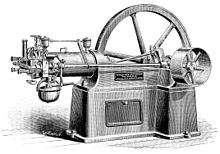
Nikolaus August Otto as a young man was a traveling salesman for a grocery concern. In his travels he encountered the internal combustion engine built in Paris by Belgian expatriate Jean Joseph Etienne Lenoir. In 1860, Lenoir successfully created a double-acting engine that ran on illuminating gas at 4% efficiency. The 18 litre Lenoir Engine produced only 2 horsepower. The Lenoir engine ran on illuminating gas made from coal, which had been developed in Paris by Philip Lebon.[1][3]
In testing a replica of the Lenoir engine in 1861 Otto became aware of the effects of compression on the fuel charge. In 1862, Otto attempted to produce an engine to improve on the poor efficiency and reliability of the Lenoir engine. He tried to create an engine that would compress the fuel mixture prior to ignition, but failed as that engine would run no more than a few minutes prior to its destruction. Many other engineers were trying to solve the problem, with no success.[3]
In 1864, Otto and Eugen Langen founded the first internal combustion engine production company, NA Otto and Cie (NA Otto and Company). Otto and Cie succeeded in creating a successful atmospheric engine that same year.[3] The factory ran out of space and was moved to the town of Deutz, Germany in 1869 where the company was renamed to Deutz Gasmotorenfabrik AG (The Deutz Gas Engine Manufacturing Company).[3] In 1872, Gottlieb Daimler was technical director and Wilhelm Maybach was the head of engine design. Daimler was a gunsmith who had worked on the Lenoir engine. By 1876, Otto and Langen succeeded in creating the first internal combustion engine that compressed the fuel mixture prior to combustion for far higher efficiency than any engine created to this time.[1]
Daimler and Maybach left their employ at Otto and Cie and developed the first high-speed Otto engine in 1883. In 1885, they produced the first automobile to be equipped with an Otto engine. The Petroleum Reitwagen used a hot-tube ignition system and the fuel known as Ligroin to become the world's first vehicle powered by an internal combustion engine. It used a four-stroke engine based on Otto's design. The following year Karl Benz produced a four-stroke engined automobile that is regarded as the first car. [4]
In 1884, Otto's company, then known as Gasmotorenfabrik Deutz (GFD), developed electric ignition and the carburetor. In 1890, Daimler and Maybach formed a company known as Daimler Motoren Gesellschaft. Today, that company is Daimler-Benz.
See Otto engine for more detail.
Diesel cycle
The diesel engine is a technical refinement of the 1876 Otto Cycle engine. Where Otto had realized in 1861 that the efficiency of the engine could be increased by first compressing the fuel mixture prior to its ignition, Rudolph Diesel wanted to develop a more efficient type of engine that could run on much heavier fuel. The Lenoir, Otto Atmospheric, and Otto Compression engines (both 1861 and 1876) were designed to run on Illuminating Gas (coal gas). With the same motivation as Otto, Diesel wanted to create an engine that would give small industrial concerns their own power source to enable them to compete against larger companies, and like Otto to get away from the requirement to be tied to a municipal fuel supply. Like Otto, it took more than a decade to produce the high compression engine that could self-ignite fuel sprayed into the cylinder. Diesel used an air spray combined with fuel in his first engine.
During initial development, one of the engines burst nearly killing Diesel. He persisted and finally created an engine in 1893. The high compression engine, which ignites its fuel by the heat of compression is now called the Diesel engine whether a four-stroke or two-stroke design.
The four-stroke diesel engine has been used in the majority of heavy duty applications for many decades. Chief among the reasons for this is that it uses a heavy fuel that contains more energy, requires less refinement, and is cheaper to make (although in some areas of the world diesel fuel costs more than gasoline). The most efficient Otto Cycle engines run near 30% efficiency. The Volkswagen Jetta TDI 1.9 liter engine achieves 46%. It uses an advanced design with turbocharging and direct fuel injection. Some BMW ship Diesels with ceramic insulation have exceeded 60% efficiency.
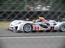
Both Audi and Peugeot compete in the endurance races of the Le Mans Series with cars having diesel engines. These are four-stroke turbocharged diesels that dominate largely due to fuel economy and having to make fewer stops.
Thermodynamic Analysis
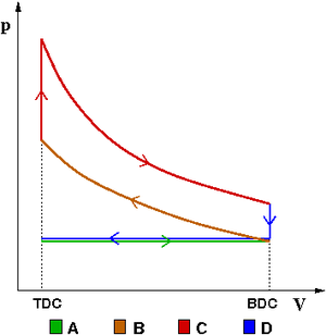
exhaust (D) stroke.
The thermodynamic analysis of the actual four-stroke or two-stroke cycles is not a simple task. However, the analysis can be simplified significantly if air standard assumptions[5] are utilized. The resulting cycle, which closely resembles the actual operating conditions, is the Otto cycle.
Octane Requirements
Fuel octane rating
Otto Engines

The fuels used in four-cycle engines are typically fractions of crude oil, coal tar, oil shale, or sands produced in a process called Petroleum Cracking. The ignition temperature of the fuel that is refracted is related to its weight. It is separated by being heated and is extracted at different heights in the refractory tower. The higher the fuel vapor rises in the tower, the lower its weight and the less energy it contains. In refracting petroleum, there is a standard weight of fuels and products that are withdrawn and associated with a specific extracted material. Gasoline is a light refractory product and is called a light fraction. As a light fraction it has a relatively low flash point (that is the temperature at which it starts to burn when mixed with an oxidizer).
A fuel with a low flash point may self-ignite during compression, and can also be ignited by carbon deposits left in the cylinder or head of a dirty engine. In an internal combustion engine self ignition can occur at unexpected times. During the normal operation of the engine as the fuel mixture is being compressed an electric arc is created to ignite the fuel. At low rpm this occurs close to TDC (Top Dead Centre). As engine rpm rises the spark point is moved forward so that the fuel charge can be ignited at a more efficient point in fuel charge compression to allow the fuel to start burning even while it is still being compressed. This produces more effective power based on the rising molecular density of the working medium, since this is the essence of efficiency in the compressed charge IE engine. A denser working medium (the air fuel mixture) experiences a greater heat, and therefore pressure, rises on less when its molecules are more densely packed together.
We can see this in two Otto engines designs. The non-compression engine operated at 12% efficiency. The compressed charge engine had an operating efficiency of 30%. A Diesel engine can reach as high as 70% (Diesel's lab engine tested at 75.6% efficiency, VW TDI is at 46%).
The problem with compressed charge engines is that the temperature rise of the compressed charge can cause pre-ignition. If this occurs at the wrong time and is too energetic, it can destroy the engine. Fractions of petroleum have widely varying flash points (the temperatures at which the fuel may self-ignite). This must be taken into account in engine and fuel design.
In engines, the spark is retarded when the engine is being started, and progresses only to an appropriate amount based on engine rpm. This is determined by laboratory research. As the engine revolves faster it can accept earlier ignition since the moving flame front does not have time to be destructive.
In fuel, the tendency for the compressed fuel mixture to ignite early is limited by the chemical composition of the fuel. There are several grades of fuel to accommodate differing performance levels of engines. The fuel is altered to change its self ignition temperature. There are several ways to do this. As engines are designed with higher compression ratios the result is that pre-ignition is much more likely to occur since the fuel mixture is compressed to a higher temperature prior to deliberate ignition. The higher temperature more effectively evaporates fuels such as gasoline, and is factor in a higher compression engine being more efficient. Higher Compression ratios also mean that the distance that the piston can push to produce power is greater (which is called the Expansion ratio).
So there must be a standardized test and a standard reference system to describe how likely a fuel is to self-ignite. The octane rating is a measure of the fuel's resistance to self-ignition. A fuel with a higher numerical octane rating allows for a higher compression ratio, which extracts more energy from the fuel and more effectively converts that energy into useful work while at the same time preventing engine damage from pre-ignition. High Octane fuel is also more expensive.
Diesel Engines
Diesel engines by their nature do not have concerns with pre-ignition. They have a concern with whether or not combustion can be started. The description of how likely Diesel fuel is to ignite is called the Cetane rating. Because Diesel fuels are of low volatility, they can be very hard to start when cold. Various techniques are used to start a cold Diesel engine, the most common being the use of a glow plug.
Design and engineering principles
Power output limitations
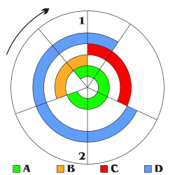
1=TDC
2=BDC
A: Intake
B: Compression
C: Power
D: Exhaust
The maximum amount of power generated by an engine is determined by the maximum amount of air ingested. The amount of power generated by a piston engine is related to its size (cylinder volume), whether it is a two-stroke or four-stroke design, volumetric efficiency, losses, air-to-fuel ratio, the calorific value of the fuel, oxygen content of the air and speed (RPM). The speed is ultimately limited by material strength and lubrication. Valves, pistons and connecting rods suffer severe acceleration forces. At high engine speed, physical breakage and piston ring flutter can occur, resulting in power loss or even engine destruction. Piston ring flutter occurs when the rings oscillate vertically within the piston grooves they reside in. Ring flutter compromises the seal between the ring and the cylinder wall, which causes a loss of cylinder pressure and power. If an engine spins too quickly, valve springs cannot act quickly enough to close the valves. This is commonly referred to as 'valve float', and it can result in piston to valve contact, severely damaging the engine. At high speeds the lubrication of piston cylinder wall interface tends to break down. This limits the piston speed for industrial engines to about 10 m/s.
Intake/exhaust port flow
The output power of an engine is dependent on the ability of intake (air–fuel mixture) and exhaust matter to move quickly through valve ports, typically located in the cylinder head. To increase an engine's output power, irregularities in the intake and exhaust paths, such as casting flaws, can be removed, and, with the aid of an air flow bench, the radii of valve port turns and valve seat configuration can be modified to reduce resistance. This process is called porting, and it can be done by hand or with a CNC machine.
Supercharging
One way to increase engine power is to force more air into the cylinder so that more power can be produced from each power stroke. This can be done using some type of air compression device known as a supercharger, which can be powered by the engine crankshaft.
Supercharging increases the power output limits of an internal combustion engine relative to its displacement. Most commonly, the supercharger is always running, but there have been designs that allow it to be cut out or run at varying speeds (relative to engine speed). Mechanically driven supercharging has the disadvantage that some of the output power is used to drive the supercharger, while power is wasted in the high pressure exhaust, as the air has been compressed twice and then gains more potential volume in the combustion but it is only expanded in one stage.
Turbocharging
A turbocharger is a supercharger that is driven by the engine's exhaust gases, by means of a turbine. It consists of a two piece, high-speed turbine assembly with one side that compresses the intake air, and the other side that is powered by the exhaust gas outflow.
When idling, and at low-to-moderate speeds, the turbine produces little power from the small exhaust volume, the turbocharger has little effect and the engine operates nearly in a naturally aspirated manner. When much more power output is required, the engine speed and throttle opening are increased until the exhaust gases are sufficient to 'spin up' the turbocharger's turbine to start compressing much more air than normal into the intake manifold.
Turbocharging allows for more efficient engine operation because it is driven by exhaust pressure that would otherwise be (mostly) wasted, but there is a design limitation known as turbo lag. The increased engine power is not immediately available due to the need to sharply increase engine RPM, to build up pressure and to spin up the turbo, before the turbo starts to do any useful air compression. The increased intake volume causes increased exhaust and spins the turbo faster, and so forth until steady high power operation is reached. Another difficulty is that the higher exhaust pressure causes the exhaust gas to transfer more of its heat to the mechanical parts of the engine.
Rod and piston-to-stroke ratio
The rod-to-stroke ratio is the ratio of the length of the connecting rod to the length of the piston stroke. A longer rod reduces sidewise pressure of the piston on the cylinder wall and the stress forces, increasing engine life. It also increases the cost and engine height and weight.
A "square engine" is an engine with a bore diameter equal to its stroke length. An engine where the bore diameter is larger than its stroke length is an oversquare engine, conversely, an engine with a bore diameter that is smaller than its stroke length is an undersquare engine.
Valve train
The valves are typically operated by a camshaft rotating at half the speed of the crankshaft. It has a series of cams along its length, each designed to open a valve during the appropriate part of an intake or exhaust stroke. A tappet between valve and cam is a contact surface on which the cam slides to open the valve. Many engines use one or more camshafts “above” a row (or each row) of cylinders, as in the illustration, in which each cam directly actuates a valve through a flat tappet. In other engine designs the camshaft is in the crankcase, in which case each cam contacts a push rod, which contacts a rocker arm that opens a valve. The overhead cam design typically allows higher engine speeds because it provides the most direct path between cam and valve.
Valve clearance
Valve clearance refers to the small gap between a valve lifter and a valve stem that ensures that the valve completely closes. On engines with mechanical valve adjustment, excessive clearance causes noise from the valve train. A too small valve clearance can result in the valves not closing properly, this results in a loss of performance and possibly overheating of exhaust valves. Typically, the clearance must be readjusted each 20,000 miles (32,000 km) with a feeler gauge.
Most modern production engines use hydraulic lifters to automatically compensate for valve train component wear. Dirty engine oil may cause lifter failure.
Energy balance
Otto engines are about 30% efficient; in other words, 30% of the energy generated by combustion is converted into useful rotational energy at the output shaft of the engine, while the remainder being losses due to waste heat, friction and engine accessories.[6] There are a number of ways to recover some of the energy lost to waste heat. The use of a Turbocharger in Diesel engines is very effective by boosting incoming air pressure and in effect provides the same increase in performance as having more displacement. The Mack Truck company, decades ago, developed a turbine system that converted waste heat into kinetic energy that it fed back into the engine's transmission. In 2005, BMW announced the development of the turbosteamer, a two stage heat recovery system similar to the Mack system that recovers 80% of the energy in the exhaust gas and raises the efficiency of an Otto engine by 15%.[7] By contrast, a six-stroke engine may convert more than 50% of the energy of combustion into useful rotational energy.
Modern engines are often intentionally built to be slightly less efficient than they could otherwise be. This is necessary for emission controls such as exhaust gas recirculation and catalytic converters that reduce smog and other atmospheric pollutants. Reductions in efficiency may be counteracted with an engine control unit using lean burn techniques.[8]
In the United States, the Corporate Average Fuel Economy mandates that vehicles must achieve an average of 35.5 miles per gallon (mpg) compared to the current standard of 25 mpg. As automakers look to meet these standards by 2016, new ways of engineering the traditional internal combustion engine (ICE) could have to be considered. Some potential solutions to increase fuel efficiency to meet new mandates include firing after the piston is farthest from the crankshaft, known as top dead centre, and applying the Miller cycle. Together, this redesign could significantly reduce fuel consumption and NOx emissions.


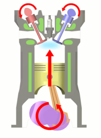
Starting position, intake stroke, and compression stroke.
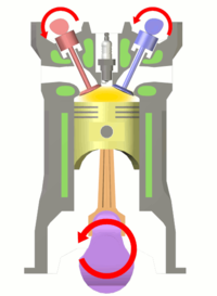
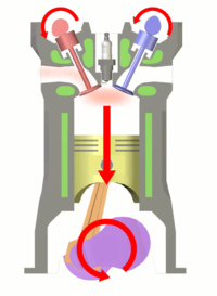
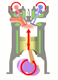
Ignition of fuel, power stroke, and exhaust stroke.
See also
- Atkinson cycle
- Desmodromic valve
- History of the internal combustion engine
- Napier Deltic
- Poppet valve
References
- ^ a b c d [1], Nikolaus August Otto: Inventor Of The Internal Combustion Engine.
- ^ Brittanica, Britannica Gasoline Engine.
- ^ a b c d [2], NA Otto Museum.
- ^ Ralph Stein (1967). The Automobile Book. Paul Hamlyn Ltd
- ^ Best Place for Engineering and Technology, Air Standard Assumptions.
- ^ Otto Engine Efficiency, Efficiencies of Internal Combustion Engines.
- ^ BMW Turbo Steamer Gets Hot and Goes, Autoblog, December 9, 2005.
- ^ Air pollution from motor vehicles By Asif Faiz, Christopher S. Weaver, Michael P. Walsh
General sources
- Hardenberg, Horst O. (1999). The Middle Ages of the Internal combustion Engine. Society of Automotive Engineers (SAE). ISBN 978-0-7680-0391-8.
- scienceworld.wolfram.com/physics/OttoCycle.html
- Cengel, Yunus A (2009). Thermodynamics An Engineering Approach. N.p. The McGraw Hill Companies. ISBN 978-7-121-08478-2.
{{cite book}}: Unknown parameter|coauthors=ignored (|author=suggested) (help) - Benson, Tom (11 July 2008). "4 Stroke Internal Combustion Engine". p. National Aeronautics and Space Administration. Retrieved 5 May 2011.
External links
- U.S. patent 194,047
- Detailed Engine Animations
- How Car Engines Work
- Animated Engines, four stroke, another explanation of the four-stroke engine.
- CDX eTextbook, some videos of car components in action.
- Video from inside a four-stroke engine cylinder
