Compressible flow
Compressible flow (or gas dynamics) is the branch of fluid mechanics that deals with flows having significant changes in fluid density. While all flows are compressible, flows are usually treated as being incompressible when the Mach number (the ratio of the speed of the flow to the speed of sound) is smaller than 0.3 (since the density change due to velocity is about 5% in that case).[1] The study of compressible flow is relevant to high-speed aircraft, jet engines, rocket motors, high-speed entry into a planetary atmosphere, gas pipelines, commercial applications such as abrasive blasting, and many other fields.
History
[edit]The study of gas dynamics is often associated with the flight of modern high-speed aircraft and atmospheric reentry of space-exploration vehicles; however, its origins lie with simpler machines. At the beginning of the 19th century, investigation into the behaviour of fired bullets led to improvement in the accuracy and capabilities of guns and artillery.[2] As the century progressed, inventors such as Gustaf de Laval advanced the field, while researchers such as Ernst Mach sought to understand the physical phenomena involved through experimentation.
At the beginning of the 20th century, the focus of gas dynamics research shifted to what would eventually become the aerospace industry. Ludwig Prandtl and his students proposed important concepts ranging from the boundary layer to supersonic shock waves, supersonic wind tunnels, and supersonic nozzle design.[2] Theodore von Kármán, a student of Prandtl, continued to improve the understanding of supersonic flow. Other notable figures (Meyer, Luigi Crocco, and Ascher Shapiro) also contributed significantly to the principles considered fundamental to the study of modern gas dynamics. Many others also contributed to this field.
Accompanying the improved conceptual understanding of gas dynamics in the early 20th century was a public misconception that there existed a barrier to the attainable speed of aircraft, commonly referred to as the "sound barrier." In truth, the barrier to supersonic flight was merely a technological one, although it was a stubborn barrier to overcome. Amongst other factors, conventional aerofoils saw a dramatic increase in drag coefficient when the flow approached the speed of sound. Overcoming the larger drag proved difficult with contemporary designs, thus the perception of a sound barrier. However, aircraft design progressed sufficiently to produce the Bell X-1. Piloted by Chuck Yeager, the X-1 officially achieved supersonic speed in October 1947.[3]
Historically, two parallel paths of research have been followed in order to further gas dynamics knowledge. Experimental gas dynamics undertakes wind tunnel model experiments and experiments in shock tubes and ballistic ranges with the use of optical techniques to document the findings. Theoretical gas dynamics considers the equations of motion applied to a variable-density gas, and their solutions. Much of basic gas dynamics is analytical, but in the modern era Computational fluid dynamics applies computing power to solve the otherwise-intractable nonlinear partial differential equations of compressible flow for specific geometries and flow characteristics.
Introductory concepts
[edit]
There are several important assumptions involved in the underlying theory of compressible flow. All fluids are composed of molecules, but tracking a huge number of individual molecules in a flow (for example at atmospheric pressure) is unnecessary. Instead, the continuum assumption allows us to consider a flowing gas as a continuous substance except at low densities. This assumption provides a huge simplification which is accurate for most gas-dynamic problems. Only in the low-density realm of rarefied gas dynamics does the motion of individual molecules become important.
A related assumption is the no-slip condition where the flow velocity at a solid surface is presumed equal to the velocity of the surface itself, which is a direct consequence of assuming continuum flow. The no-slip condition implies that the flow is viscous, and as a result a boundary layer forms on bodies traveling through the air at high speeds, much as it does in low-speed flow.
Most problems in incompressible flow involve only two unknowns: pressure and velocity, which are typically found by solving the two equations that describe conservation of mass and of linear momentum, with the fluid density presumed constant. In compressible flow, however, the gas density and temperature also become variables. This requires two more equations in order to solve compressible-flow problems: an equation of state for the gas and a conservation of energy equation. For the majority of gas-dynamic problems, the simple ideal gas law is the appropriate state equation. Otherwise, more complex equations of state must be considered and the so-called non ideal compressible fluids dynamics (NICFD) establishes.
Fluid dynamics problems have two overall types of references frames, called Lagrangian and Eulerian (see Joseph-Louis Lagrange and Leonhard Euler). The Lagrangian approach follows a fluid mass of fixed identity as it moves through a flowfield. The Eulerian reference frame, in contrast, does not move with the fluid. Rather it is a fixed frame or control volume that fluid flows through. The Eulerian frame is most useful in a majority of compressible flow problems, but requires that the equations of motion be written in a compatible format.
Finally, although space is known to have 3 dimensions, an important simplification can be had in describing gas dynamics mathematically if only one spatial dimension is of primary importance, hence 1-dimensional flow is assumed. This works well in duct, nozzle, and diffuser flows where the flow properties change mainly in the flow direction rather than perpendicular to the flow. However, an important class of compressible flows, including the external flow over bodies traveling at high speed, requires at least a 2-dimensional treatment. When all 3 spatial dimensions and perhaps the time dimension as well are important, we often resort to computerized solutions of the governing equations.
Mach number, wave motion, and sonic speed
[edit]The Mach number (M) is defined as the ratio of the speed of an object (or of a flow) to the speed of sound. For instance, in air at room temperature, the speed of sound is about 340 m/s (1,100 ft/s). M can range from 0 to ∞, but this broad range falls naturally into several flow regimes. These regimes are subsonic, transonic, supersonic, hypersonic, and hypervelocity flow. The figure below illustrates the Mach number "spectrum" of these flow regimes.
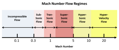
These flow regimes are not chosen arbitrarily, but rather arise naturally from the strong mathematical background that underlies compressible flow (see the cited reference textbooks). At very slow flow speeds the speed of sound is so much faster that it is mathematically ignored, and the Mach number is irrelevant. Once the speed of the flow approaches the speed of sound, however, the Mach number becomes all-important, and shock waves begin to appear. Thus the transonic regime is described by a different (and much more complex) mathematical treatment. In the supersonic regime the flow is dominated by wave motion at oblique angles similar to the Mach angle. Above about Mach 5, these wave angles grow so small that a different mathematical approach is required, defining the hypersonic speed regime. Finally, at speeds comparable to that of planetary atmospheric entry from orbit, in the range of several km/s, the speed of sound is now comparatively so slow that it is once again mathematically ignored in the hypervelocity regime.
As an object accelerates from subsonic toward supersonic speed in a gas, different types of wave phenomena occur. To illustrate these changes, the next figure shows a stationary point (M = 0) that emits symmetric sound waves. The speed of sound is the same in all directions in a uniform fluid, so these waves are simply concentric spheres. As the sound-generating point begins to accelerate, the sound waves "bunch up" in the direction of motion and "stretch out" in the opposite direction. When the point reaches sonic speed (M = 1), it travels at the same speed as the sound waves it creates. Therefore, an infinite number of these sound waves "pile up" ahead of the point, forming a Shock wave. Upon achieving supersonic flow, the particle is moving so fast that it continuously leaves its sound waves behind. When this occurs, the locus of these waves trailing behind the point creates an angle known as the Mach wave angle or Mach angle, μ:
where represents the speed of sound in the gas and represents the velocity of the object. Although named for Austrian physicist Ernst Mach, these oblique waves were first discovered by Christian Doppler.[4]

One-dimensional flow
[edit]One-dimensional (1-D) flow refers to flow of gas through a duct or channel in which the flow parameters are assumed to change significantly along only one spatial dimension, namely, the duct length. In analysing the 1-D channel flow, a number of assumptions are made:
- Ratio of duct length to width (L/D) is ≤ about 5 (in order to neglect friction and heat transfer),
- Steady vs. Unsteady Flow,
- Flow is isentropic (i.e. a reversible adiabatic process),
- Ideal gas law (i.e. P = ρRT)
Converging-diverging Laval nozzles
[edit]As the speed of a flow accelerates from the subsonic to the supersonic regime, the physics of nozzle and diffuser flows is altered. Using the conservation laws of fluid dynamics and thermodynamics, the following relationship for channel flow is developed (combined mass and momentum conservation):
- ,
where dP is the differential change in pressure, M is the Mach number, ρ is the density of the gas, V is the velocity of the flow, A is the area of the duct, and dA is the change in area of the duct. This equation states that, for subsonic flow, a converging duct (dA < 0) increases the velocity of the flow and a diverging duct (dA > 0) decreases velocity of the flow. For supersonic flow, the opposite occurs due to the change of sign of (1 − M2). A converging duct (dA < 0) now decreases the velocity of the flow and a diverging duct (dA > 0) increases the velocity of the flow. At Mach = 1, a special case occurs in which the duct area must be either a maximum or minimum. For practical purposes, only a minimum area can accelerate flows to Mach 1 and beyond. See table of sub-supersonic diffusers and nozzles.

Therefore, to accelerate a flow to Mach 1, a nozzle must be designed to converge to a minimum cross-sectional area and then expand. This type of nozzle – the converging-diverging nozzle – is called a de Laval nozzle after Gustaf de Laval, who invented it. As subsonic flow enters the converging duct and the area decreases, the flow accelerates. Upon reaching the minimum area of the duct, also known as the throat of the nozzle, the flow can reach Mach 1. If the speed of the flow is to continue to increase, its density must decrease in order to obey conservation of mass. To achieve this decrease in density, the flow must expand, and to do so, the flow must pass through a diverging duct. See image of de Laval Nozzle.

Maximum achievable velocity of a gas
[edit]Ultimately, because of the energy conservation law, a gas is limited to a certain maximum velocity based on its energy content. The maximum velocity, Vmax, that a gas can attain is:
where cp is the specific heat of the gas and Tt is the stagnation temperature of the flow.
Isentropic flow Mach number relationships
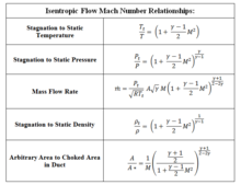
[edit]Using conservations laws and thermodynamics, a number of relationships of the form
can be obtained, where M is the Mach number and γ is the ratio of specific heats (1.4 for air). See table of isentropic flow Mach number relationships.
Achieving supersonic flow
[edit]As previously mentioned, in order for a flow to become supersonic, it must pass through a duct with a minimum area, or sonic throat. Additionally, an overall pressure ratio, Pb/Pt, of approximately 2 is needed to attain Mach 1. Once it has reached Mach 1, the flow at the throat is said to be choked. Because changes downstream can only move upstream at sonic speed, the mass flow through the nozzle cannot be affected by changes in downstream conditions after the flow is choked.
Non-isentropic 1D channel flow of a gas - normal shock waves
[edit]Normal shock waves are shock waves that are perpendicular to the local flow direction. These shock waves occur when pressure waves build up and coalesce into an extremely thin shockwave that converts kinetic energy into thermal energy. The waves thus overtake and reinforce one another, forming a finite shock wave from an infinite series of infinitesimal sound waves. Because the change of state across the shock is highly irreversible, entropy increases across the shock. When analysing a normal shock wave, one-dimensional, steady, and adiabatic flow of a perfect gas is assumed. Stagnation temperature and stagnation enthalpy are the same upstream and downstream of the shock.

Normal shock waves can be easily analysed in either of two reference frames: the standing normal shock and the moving shock. The flow before a normal shock wave must be supersonic, and the flow after a normal shock must be subsonic. The Rankine-Hugoniot equations are used to solve for the flow conditions.
Two-dimensional flow
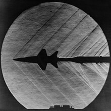
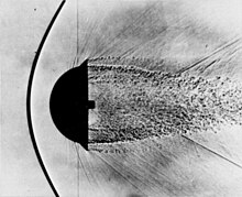
[edit]Although one-dimensional flow can be directly analysed, it is merely a specialized case of two-dimensional flow. It follows that one of the defining phenomena of one-dimensional flow, a normal shock, is likewise only a special case of a larger class of oblique shocks. Further, the name "normal" is with respect to geometry rather than frequency of occurrence. Oblique shocks are much more common in applications such as: aircraft inlet design, objects in supersonic flight, and (at a more fundamental level) supersonic nozzles and diffusers. Depending on the flow conditions, an oblique shock can either be attached to the flow or detached from the flow in the form of a bow shock.
 |
 |
Oblique shock waves
[edit]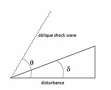
Oblique shock waves are similar to normal shock waves, but they occur at angles less than 90° with the direction of flow. When a disturbance is introduced to the flow at a nonzero angle (δ), the flow must respond to the changing boundary conditions. Thus an oblique shock is formed, resulting in a change in the direction of the flow.
Shock polar diagram
[edit]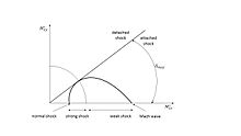
Based on the level of flow deflection (δ), oblique shocks are characterized as either strong or weak. Strong shocks are characterized by larger deflection and more entropy loss across the shock, with weak shocks as the opposite. In order to gain cursory insight into the differences in these shocks, a shock polar diagram can be used. With the static temperature after the shock, T*, known the speed of sound after the shock is defined as,
with R as the gas constant and γ as the specific heat ratio. The Mach number can be broken into Cartesian coordinates
with Vx and Vy as the x and y-components of the fluid velocity V. With the Mach number before the shock given, a locus of conditions can be specified. At some δmax, the flow transitions from a strong to weak oblique shock. With δ = 0°, a normal shock is produced at the limit of the strong oblique shock and the Mach wave is produced at the limit of the weak shock wave.
Oblique shock reflection
[edit]Due to the inclination of the shock, after an oblique shock is created, it can interact with a boundary in three different manners, two of which are explained below.
Solid boundary
[edit]Incoming flow is first turned by angle δ with respect to the flow. This shockwave is reflected off the solid boundary, and the flow is turned by – δ to again be parallel with the boundary. Each progressive shock wave is weaker and the wave angle is increased.
Irregular reflection
[edit]An irregular reflection is much like the case described above, with the caveat that δ is larger than the maximum allowable turning angle. Thus a detached shock is formed and a more complicated reflection known as Mach reflection occurs.
Prandtl–Meyer fans
[edit]Prandtl–Meyer fans can be expressed as both compression and expansion fans. Prandtl–Meyer fans also cross a boundary layer (i.e. flowing and solid) which reacts in different changes as well. When a shock wave hits a solid surface the resulting fan returns as one from the opposite family while when one hits a free boundary the fan returns as a fan of opposite type.
Prandtl–Meyer expansion fans
[edit]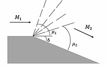
To this point, the only flow phenomena that have been discussed are shock waves, which slow the flow and increase its entropy. It is possible to accelerate supersonic flow in what has been termed a Prandtl–Meyer expansion fan, after Ludwig Prandtl and Theodore Meyer. The mechanism for the expansion is shown in the figure below.
As opposed to the flow encountering an inclined obstruction and forming an oblique shock, the flow expands around a convex corner and forms an expansion fan through a series of isentropic Mach waves. The expansion "fan" is composed of Mach waves that span from the initial Mach angle to the final Mach angle. Flow can expand around either a sharp or rounded corner equally, as the increase in Mach number is proportional to only the convex angle of the passage (δ). The expansion corner that produces the Prandtl–Meyer fan can be sharp (as illustrated in the figure) or rounded. If the total turning angle is the same, then the P-M flow solution is also the same.
The Prandtl–Meyer expansion can be seen as the physical explanation of the operation of the Laval nozzle. The contour of the nozzle creates a smooth and continuous series of Prandtl–Meyer expansion waves.
Prandtl–Meyer compression fans
[edit]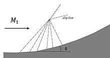
A Prandtl–Meyer compression is the opposite phenomenon to a Prandtl–Meyer expansion. If the flow is gradually turned through an angle of δ, a compression fan can be formed. This fan is a series of Mach waves that eventually coalesce into an oblique shock. Because the flow is defined by an isentropic region (flow that travels through the fan) and an anisentropic region (flow that travels through the oblique shock), a slip line results between the two flow regions.
Applications
[edit]Supersonic wind tunnels
[edit]Supersonic wind tunnels are used for testing and research in supersonic flows, approximately over the Mach number range of 1.2 to 5. The operating principle behind the wind tunnel is that a large pressure difference is maintained upstream to downstream, driving the flow.

Wind tunnels can be divided into two categories: continuous-operating and intermittent-operating wind tunnels. Continuous operating supersonic wind tunnels require an independent electrical power source that drastically increases with the size of the test section. Intermittent supersonic wind tunnels are less expensive in that they store electrical energy over an extended period of time, then discharge the energy over a series of brief tests. The difference between these two is analogous to the comparison between a battery and a capacitor.
 |
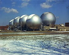 |
Blowdown type supersonic wind tunnels offer high Reynolds number, a small storage tank, and readily available dry air. However, they cause a high pressure hazard, result in difficulty holding a constant stagnation pressure, and are noisy during operation.
Indraft supersonic wind tunnels are not associated with a pressure hazard, allow a constant stagnation pressure, and are relatively quiet. Unfortunately, they have a limited range for the Reynolds number of the flow and require a large vacuum tank.
There is no dispute that knowledge is gained through research and testing in supersonic wind tunnels; however, the facilities often require vast amounts of power to maintain the large pressure ratios needed for testing conditions. For example, Arnold Engineering Development Complex has the largest supersonic wind tunnel in the world and requires the power required to light a small city for operation. For this reason, large wind tunnels are becoming less common at universities.
Supersonic aircraft inlets
[edit]Perhaps the most common requirement for oblique shocks is in supersonic aircraft inlets for speeds greater than about Mach 2 (the F-16 has a maximum speed of Mach 2 but doesn't need an oblique shock intake). One purpose of the inlet is to minimize losses across the shocks as the incoming supersonic air slows down to subsonic before it enters the turbojet engine. This is accomplished with one or more oblique shocks followed by a very weak normal shock, with an upstream Mach number usually less than 1.4. The airflow through the intake has to be managed correctly over a wide speed range from zero to its maximum supersonic speed. This is done by varying the position of the intake surfaces.
Although variable geometry is required to achieve acceptable performance from take-off to speeds exceeding Mach 2 there is no one method to achieve it. For example, for a maximum speed of about Mach 3, the XB-70 used rectangular inlets with adjustable ramps and the SR-71 used circular inlets with adjustable inlet cone.
 |
 |
See also
[edit]- Incompressible flow
- Conservation laws
- Entropy
- Equation of state
- Gas kinetics
- Heat capacity ratio
- Isentropic nozzle flow
- Lagrangian and Eulerian specification of the flow field
- Prandtl–Meyer function
- Thermodynamics especially "Commonly Considered Thermodynamic Processes" and "Laws of Thermodynamics"
- Non-ideal compressible fluid dynamics
References
[edit]- ^ Anderson, J.D., Fundamentals of Aerodynamics, 4th Ed., McGraw–Hill, 2007.
- ^ a b Genick Bar–Meir (May 21, 2007). "Fundamentals of Compressible Fluid Mechanics" (PDF). ibiblio (Potto Project). Retrieved January 23, 2020.>
- ^ Anderson, John D. Jr. "Research in Supersonic Flight and the Breaking of the Sound Barrier". history.nasa.gov. Archived from the original on 25 December 2017. Retrieved 14 April 2018.
- ^ P. M. Schuster:Moving the Stars: Christian Doppler - His Life, His Works and Principle and the World After, Pollauberg, Austria:Living Edition Publishers, 2005
- Liepmann, Hans W.; Roshko, A. (1957) [1957]. Elements of Gasdynamics. Dover Publications. ISBN 0-486-41963-0.
- Anderson, John D. Jr. (2003) [1982]. Modern Compressible Flow (3rd ed.). McGraw-Hill Science/Engineering/Math. ISBN 0-07-242443-5.
- John, James E.; Keith, T. G. (2006) [1969]. Gas Dynamics (3rd ed.). Prentice Hall. ISBN 0-13-120668-0.
- Oosthuizen, Patrick H.; Carscallen, W. E. (2013) [1997]. Introduction to Compressible Flow (2nd ed.). CRC Press. ISBN 978-1439877913.
- Zucker, Robert D.; Biblarz, O. (2002) [1977]. Fundamentals of Gas Dynamics (2nd ed.). Wiley. ISBN 0471059676.
- Shapiro, Ascher H. (1953). The Dynamics and Thermodynamics of Compressible Fluid Flow, Volume 1. Ronald Press Company. ISBN 978-0-471-06691-0.
- Anderson, John D. Jr. (2000) [1989]. Hypersonic and High Temperature Gas Dynamics. AIAA. ISBN 1-56347-459-X.


